Some words:
Building of astronomic telescope mirrors become dramatically easier, when Leon Foucault - an french physicist - made his famous invention at the end of the 16th century. The invention makes it possible to test the surface of a spherical mirror in unknown accuracy, using a simple tool that nearly everybody can make by themself!
Enclosed you'll find some tool that I've built for testing of astronimical mirrors:
* Foucault tester with fixed light source
* Measuring table with linear support
* Slitless Foucault tester
* Artificial star
* Calculation of the balance point and of the flexural stiffness
.
click on the pictures to see them with higher solution|
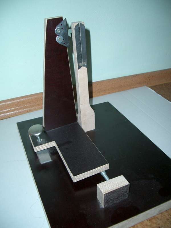
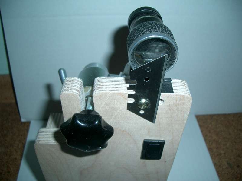
Foucault tester with fixed light source (my 1st tester) The
tester is made of wood, similar to plywood. This material will normaly
be used to lag concrete walls. I got a oddment in a DIY-store, but you
can take also other wood. This material has the benefit that it does
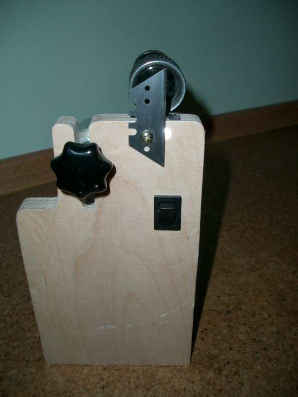
not swell when getting wet, therefor it is not neccessary to varnish it. The principle: In the light-coloured upright strut a ultra-bright LED is stored, before the lamp there are two smal blades that can be put together as closely as neccessary to result a smal light slit (smaler than 0.004 inch). The light will be ratiocinated from the mirror. You have to align the mirror that way, that the light will be ratiocinated to the knifeegdge on the trut beside. The knifeedge can be moved: |
|||
|
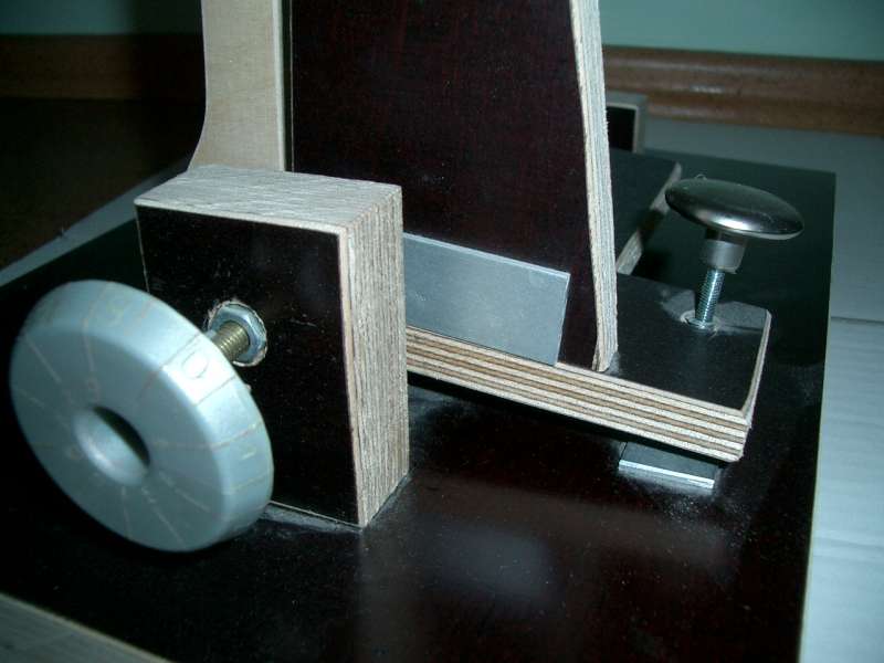
Movement To pivot a simple drawer-know will be used. The tread is a screwed insert. By moving the infeed slides the round grindend head of the winding will slide on a smal peace of aluminium. To measure the zones of a mirror you have to be as precise as possible. How to do without having a dial gauge? The trick: using the right thread you can achieve that by turning once the test slide will move a exactly known distance. In my case I used a M6 thread that moves exactly 1 millimeter per turn. To be able to read the moving exactly I mounted a big selfmade screwhead at the thread. Dividing the radius by 20 I can read movements to 1/20mm |
|||
|
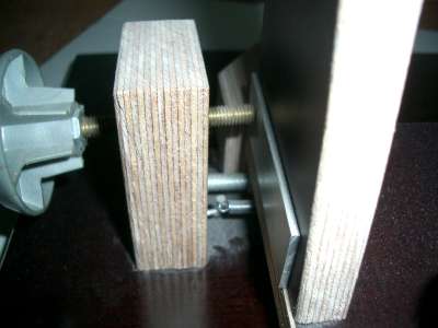
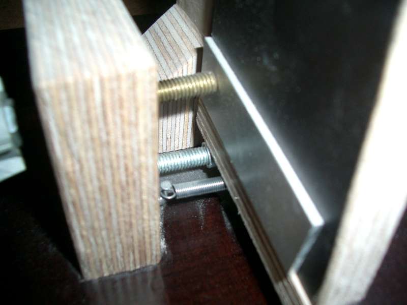
It is neccessary that the tester becomes free from backlash. The "sledge" is glued on a 8mm aluminium-pipe that is put on a truss. The truss is fixed by two smal wooden blocks. A spring pulls the sledge to the thread, resulting no backlash. This truss is the axis for pivoting the whole test sled. |
|||
|
To become a stable rigid support for the threadhead, the round-grinded head runs on smal metal sheet. |
|||
|
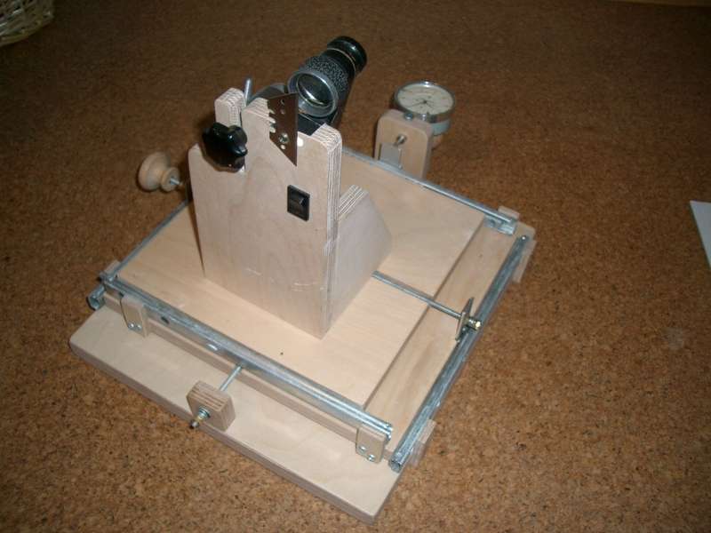
Measuring table with
linear support This is a very clever device. You only have to place the needed test equipment on it, then you can move it while reading distances over two axis very precisely. On the picture you can see my slitless foucault tester on it. The principle: on a massive wooden plate made of 1" baltic birch plywood there are two wooden plates mounted. Both will be hold by two linear bearings each. The linear bearings are from a DIY-store, normally used for drawers. The movement results via threaded bolts with 0.15" diameter that are fixed on the layer below.
|
|||
|
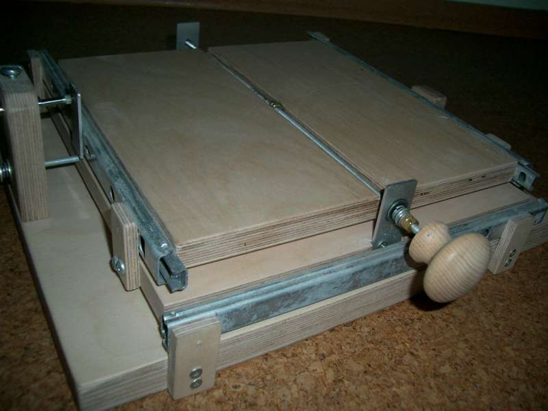
To avoid unwished tipping, the driving power will be assigned via a pair of nuts, that are glued in the centre of each wooden board. As the threaded bolts are routed trough channels in the boards, the face of the top board is flat and can be used to store and move any kind of test equipment on it. The mountings of the thread bolts do not have a thread itsef, the only thread is in the nuts, that are glued in the centre of the boards. Turning the bolts will move the boards, but not the bolt itself. |
|||
|
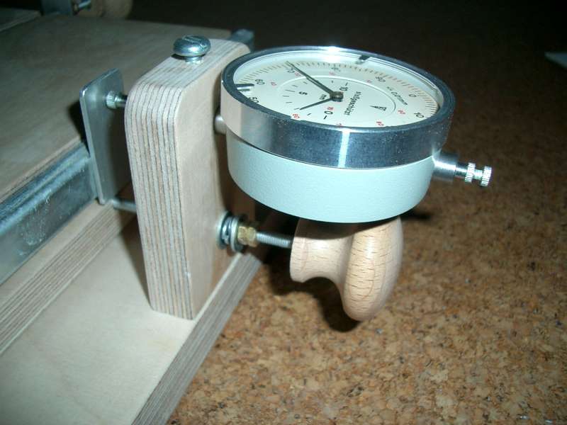
Dial Gauge When placing a full Foucault tester on the "table" you automaticaly get a tester with moving light source. Advantage: the distance to be measured between the zones will be divided by two. With a gauge with 10mm measured displacement you can read distances that otherwise can only be read with a gauge with 20mm measured displacement (that is much more expensive) Disadvantage: You have to measure with doubled accuracy. But in realtity the limiting factor is not measuring from the Dial gauge but realising, when two zones are exactly equal bright. I bought my Dial Gauge via E-Bay for 13 Euro, it was produced in the 1980's in the former "DDR" the German democratic republic that was part of the Eastern Block. |
|||
|
Slitless Foucaulttester - general things What is a slitless tester? Well, in this case the light source will be screened off not until only a very small slit can be seen, but only one half of the light source will be shadowed by a knife-edge. The trick: foucault testing still works,
when you use the same knife-edge to shadowing the reflected light
back from the mirror. The advantage: you can do foucault
testing without darkening the room, there is enough light
back to do it by normal daylight. |
|||
|
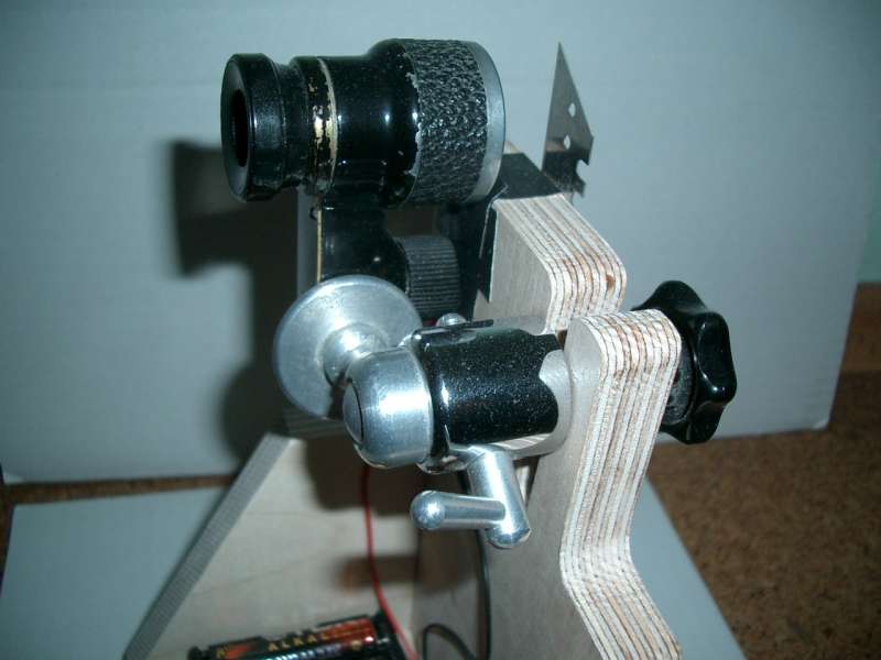
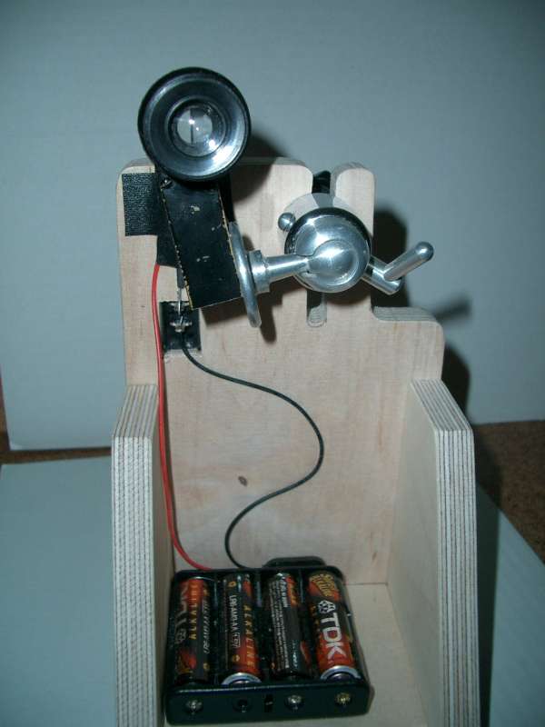
My Tester The light source is a ultra-bright LED, sourced with 4 AA-Batteries. But don't forget the right resistor between, otherwise the lamp will live only a few seconds. To achieve a uniform light, I grinded the LED with fine grinding-paper. I've integrated a swith in the front board for turning on and off. To see all details on the mirror I'm using one half of an old lorgnette I bought via E-bay. It has a magnification of aproximately 3 to 4. |
|||
|
Details How to fix the lorgnette flexible? I already had a ball joint (normaly for cameras) in stock, this a 1st choice for problems like that. Then you can choose the declination as you need to aim to the mirror. |
|||
|
Thanks of the table with the linear support the alignment of the foucault tester is very simple. You only have to put the tester on the measure table in the aproximately distance of the mirror curvature. Using a colimination bolt at the mirror support you can bring the mirror in the correct declination. Now the light comming from the lamp will be reflected in the high of the knive, just above the wood of the foucault tester. Now you can move the Foucault tester on the measure table by hand, until the light comes directly on the knife edge. The fine adjustment will be done with the threaded bolts, distances can be read via the dial gauge. .
|
|||
|
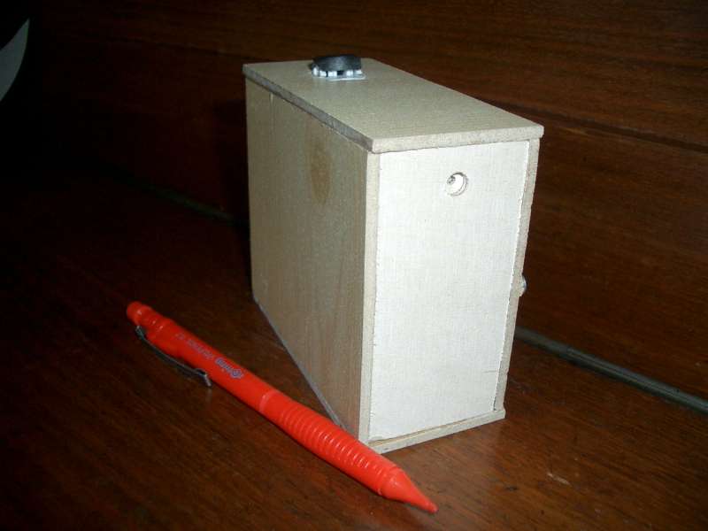
Artificial Star An artifical star can be used for coliminating your telescope or for making a star test. You need a extremely small light source, that is still relatively bright. In my case I used optical fibre. The light source is an ulta-bright LED. I drilled a smal hole in the LED, very close to the lightsource. Then I glued the cut fiber optical cable in this hole. I fixed it additionally with shrinkable tubing. For star-testing of smal telescopes a distance of some yards is enough, for bigger apperture the distance has to be relatively big to avoid relevant spherical abberation. In case of an 4" f/4 telescope aprox 10 yeards are enough, for a 20" f/5 telescope it has to be more than 200 yards to keep the failure out of the testing build-up below Lamda/6 p/v wavefront. For adjusting purposes a distance of some yards is enough also for big telescopes. |
|||
|
The front end of the optical fibre is a pin-connetor. The big advantage ot this is an absolutely round light source with a diameter of 0.002", bright enough for colominating and still bright enough for star testing with 100 yards distance. The whole stuff is put in smal a self wooden box with a switch on the top.
|
|||
|
Table for calulating
the siffness of trusses The same Excel-file contains (in a separate
tab) a sheet for calculation the flexural stiffness of tubes. You can
calculate square tubes with pipes an see, what effect a gradual change
in diameter or wall thickness has on the stiffness. You'll realise easily, that the diameter is
the most sensitive factor, much more that the thickness of the wall. check that you've choosen the right tab! |
 < >
< > < >
< > < >
< > < >
< > < >
< > < >
< > < >
< > < >
< > < >
< > <
>
<
> <
>
<
> < >
< > < >
< >Further accessories will follow soon ..